All NRG 10 and 20 Amp genset battery chargers include five alarm relays. What does each alarm mean? How can you create a summary alarm? This tech tip provides the answers.
The remote relays on NRG battery chargers monitor five individual alarm conditions. Each of the five relays has a three-position terminal block with Common, OK and Fail connections.
Normally Closed and Normally Open Alarm Systems
Normally Closed alarm configurations use the Common and OK connections. Normally Closed means that inside the relay, when the charger is operating properly, the Common and OK contacts are normally connected (closed). When a failure condition occurs, the relay changes state such that its Common and Fail contacts connect, and the Common and OK connection is lost (open). In this case the remote panel senses the open circuit and activates the remote alarm condition.
Normally Open configurations use the Common and Fail connections. In normal operation, Common and Fail contacts inside the relay are not connected; only in a failure condition do they close. In this case, the remote alarm panel operates such that a closed electrical connection shows that an alarm condition has occurred.
NRG Alarm Conditions
The NRG’s five alarms will activate as follows:
Low DC (Battery): The DC voltage at the DC terminals of the charger is below 12.0 volts when the charger is in 12 volt mode, or 24 volts when the charger is in 24 volt mode
High DC (Battery): The DC voltage at the DC terminals of the charger is above 16.0 volts when the charger is in 12 volt mode, or 32 volts when the charger is in 24 volt mode
Charger Fail: This alarm will activate when the charger has both AC power and a connected battery while sensing that the charger is not able to provide proper DC amperage. This is not a summary alarm; it only alarms if the charger itself is unable to provide the proper output.
AC FAIL: The charger has lost AC voltage or the 110-120/208-240VAC selector switch does not match the AC line voltage.
Battery fault: There are four possible causes for this alarm: (1)There is no battery connected to the charger. (2) A mismatched battery is connected to the charger; either a 12V battery is connected to a charger configured for 24V or a 24V battery is connected to a charger set up for 12V. (3) The proper battery is connected, but it is severely discharged (See “Jump” feature in owner’s manual to resolve the issue). (4) Reverse battery connection at the DC terminals of the charger.
How to Wire a Summary Alarm
If the installation requires a summary alarm, connect the individual alarms required for the summary together as follows:
For a Normally Closed alarm system, wire the individual relays in series. Connect the OK terminal of the first relay to the Common terminal of the next relay, and so forth down the line of contacts. Leave the last OK open. Include only the alarms you want in the summary. Run wires from the blank Common and the blank OK terminal to the alarm panel. See Diagram 1.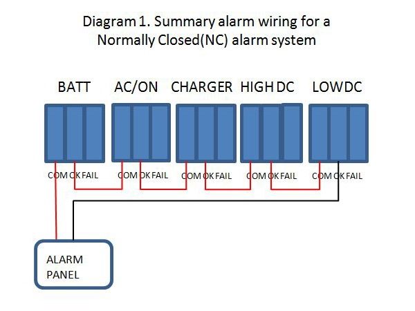
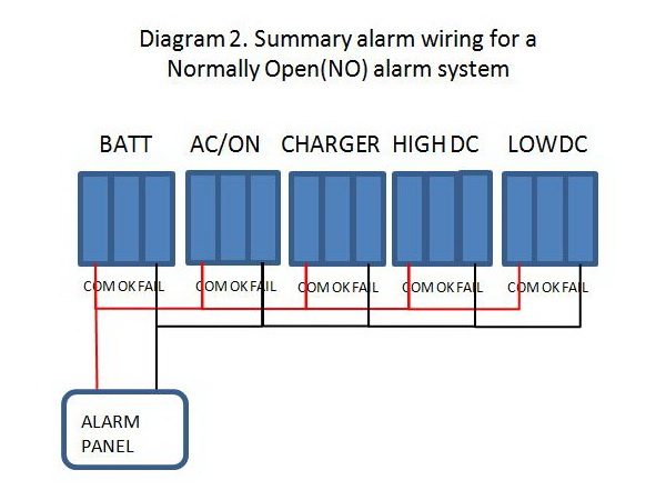
For a Normally Open alarm system, wire the relays in parallel. Connect each of the Commons together and then each of the Fails together. Then, from one Common terminal and one Fail terminal run the wires to the alarm panel. See Diagram 2.