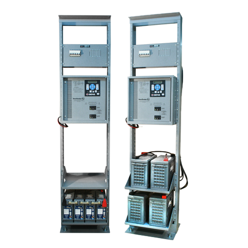
DC PowerRack™ Relay Rack System
SENS DC PowerRack™ is a complete DC power system in a 19″ relay, factory-integrated and ready to install. Because SENS PowerRack ships assembled*, it can radically cut DC system installation time, cost, and risk. It is suitable for virtually any indoor application or load requiring non-stop DC power up to 48 volts DC.
*batteries ship strapped to system pallet for installation on site.
Have Questions or Need Help?
The SENS team is here to help you through your PowerRack™ Relay Rack System journey. If you have questions or need help, reach out and start a conversation.
Complete Non-Stop DC Power System
- Includes battery charger, battery, DC distribution
- Sturdy powder-coated 19″ EIA steel rack
- 12, 24 & 48 volt systems with front or top terminal batteries
- Optional battery string breakers, sinewave inverter
- Configured to customer requirements, yet ships pre-assembled
- Single source convenience
DC PowerRack™ Relay Rack System
Applications
-
Critical process control power, ideal for control buildings at well-head pads & pipeline stations
-
48 volt switchgear applications
-
Communications
-
1. INTRODUCTION
1. INTRODUCTION
1.1. This specification defines an engine starting system consisting of integrated internal nickel-zinc battery bank, dedicated charger, controls, and communications. System shall provide reliable engine starting power to industrial engines.
-
2. AGENCY STANDARDS AND CERTIFICATIONS
2.1. Safety Agency Standards
2.1.1. Power components are UL Listed/Recognized for the United States (ULUS) and Canada
(CUL)2.1.2. NFPA 70
2.2. FCC Standards Emissions
2.2.1. 47-CFR-15 (FCC Part 15) Class B
2.3. Electrical Transient
2.3.1. ANSI/IEEE C62.41, EN 61000-4-12 on power terminals, IEC 61000-6-5 and ANSI/IEEE
C37.902.4. Vibration and Shock
2.4.1. Swept Sine (EN60068-2-6): 4G, 18-500 Hz, 3 axes. Random: 20-500Hz, .01G2
/Hz. Shock: EN 60068-2-27 (15G)2.5. Electrical Transient
2.5.1. ANSI/IEEE C62.41 & EN 61000-4-12 on power terminals
2.6. European Union (CE)
2.6.1. EMC: 2014/30/EU (EN 61000-6-2 and EN 61000-6-4)
2.6.2. LVD: 2014/35/EU (EN 60335-1 and EN 60335-2-29)
2.6.3. RoHS: 2011/65/EU (EN 50581)
2.7. Seismic
2.7.1. Seismic: Rigid base mount; max Sds of 2.5g. Certified to IBC 2000 - 2021 and California Building Code 2007 – 2021.
-
3. AC MAINS SUPPLY
3. AC MAINS SUPPLY
3.1. The AC input voltage range shall be 90-265VAC.
3.2. The AC input frequency range shall be 47-63Hz.
3.3. Charging system efficiency shall be 90% or greater.
3.4. The charging system shall provide active power factor correction. The power factor shall be at
least 0.95 or greater at maximum charging power.3.5. Supplementary overcurrent protection fuse, transient protected to EN 61000-4-5 level 4
-
4. BATTERY
4. BATTERY
4.1. The internal battery shall be nickel-zinc chemistry.
4.2. The system shall be available in 12V and 24V models.
4.3. The onboard battery shall have a minimum capacity of 80Ah.
-
5. BATTERY CHARGING
5. BATTERY CHARGING
5.1. The onboard battery charger shall have custom charging algorithms specifically designed for use
with nickel-zinc batteries.5.2. The charging algorithms shall be specifically approved by the nickel-zinc battery manufacturer.
5.3. Internal battery temperature charging compensation shall be standard.
5.4. The onboard battery charger shall be able to completely recharge the batteries within 8 hours.
5.5. The onboard battery charger shall have an output current of 12A minimum.
SuperTorque 8Z® Product5.6. The charging ripple shall not exceed 30mV.
-
6. DC OUTPUT
6. DC OUTPUT
6.1. Output Current
6.1.1. Locked Rotor Performance (breakaway current condition)
6.1.1.1. The unit shall provide breakaway currents of 2000A or greater.
6.1.1.2. For 12V starting systems, the locked-rotor voltage shall not drop below 5.0VDC
during the locked-rotor condition.6.1.1.3. For 24V starting systems, the locked-rotor voltage shall not drop below 10.0VDC
during the locked-rotor condition.6.1.2. Engine Cranking Performance (rolling current condition)
6.1.2.1. The unit shall provide engine cranking (rolling) currents of up to 1000A.
6.1.2.2. For 12V starting systems, the cranking voltage shall not drop below 9.5VDC during
cranking.6.1.2.3. For 24V starting systems, the cranking voltage shall not drop below 19.0VDC during
cranking.6.1.3. Shall meet NFPA 110 engine cranking performance requirements (note: NFPA 110 (2022) requirement that the batteries must be either lead-acid or nickel-cadmium excepted).
-
7. PARALLELING AND REDUNDANCY
7.1. The engine starting system shall support connection in parallel with two or more systems for increased starting capacities and redundancy.
7.2. The engine starting system shall support integration with Best Battery Selectors or battery isolators.
7.3. The engine starting system shall be useable in conjunction with lead-acid, nickel-cadmium or other battery types when coupled through a best battery selector.
-
8. ENVIRONMENTAL
8. ENVIRONMENTAL
8.1. The engine starting system shall operate from -10°C to 55°C.
8.2. The engine system shall be stored in temperatures from -20°C to 60°C.
8.3. Ingress Protection
8.3.1. The ingress protection shall be IP22, NEMA 3R, and UL “Rainproof”
8.3.2. Charger shall have internal ingress protection such that all AC and communications connections are non-exposed and protected from incidental jarring.
8.4. The engine starting system shall operate in humidity levels ranging from 0% to 95%, noncondensing.
8.5. The engine starting system shall operate at full specification from 0 to 13,000 ft, or 0 to 4000m above sea level.
8.6. The engine starting system shall be cooled via natural convection with no internal fans.
-
9. OPTIONS
9. OPTIONS
9.1. Floormount brackets for bolted mounting
9.2. SAE Battery Posts for DC connections
9.3. Keypad user interface and display
9.4. Communication
9.5. Field wiring kit including
-
10. USER INTERFACE
10. USER INTERFACE
10.1. The base level user interface shall provide a multicolor LED panel showing system status.
10.2. The optional level user interface shall include a backlit LCD displaying plain language text, a multicolor LED panel showing system status, and a user control panel.
10.2.1. System shall be equipped with a 1% accuracy meter for indicating AC input and DC output voltage and 1% accuracy meter for indicating DC charging current.
10.3. User interface shall ensure that users cannot change settings that would damage the battery.
-
11. REMOTE COMMUNICATIONS
11.1. Standard Communications
11.1.1. (2) Form-C Alarm Relay Contacts
11.1.1.1. Alarm relay contacts shall be customizable to support customer-specific alarm
combinations and setpoints.11.1.2. USB-C
11.1.2.1. A Setup Utility shall be available providing a custom configuration and diagnostics software utility that runs on a Windows PC via USB-C or an ethernet port.
11.2. Optional Communications
11.2.1. J1939
11.2.2. Modbus RS-485
11.2.3. Modbus TCP/IP
11.2.4. Ethernet
11.3. Custom alarm profiles shall be supported which allow the alarm relay and communications
settings to be assigned at the factory according to the specific customer requirements.11.4. Alarms
11.4.1. Any alarm indication shall cause plain language text to appear on the LCD and change appropriate LEDs. Normal LED indication shall be green. Alarm LEDs shall be red. Warning LEDs shall be amber. Multiple alarms result in the relevant LEDs changing color and multiple alarm message screens on the LCD. Alarm status shall also be available via communication interfaces.
11.4.2. The following alarms shall be provided, and shall be made assignable to any relay:
11.4.2.1. AC Line Failure
11.4.2.2. High DC Voltage
11.4.2.3. Battery on Discharge
11.4.2.4. Low DC Voltage
11.4.2.5. Battery End of Discharge
11.4.2.6. Charger Fail
11.4.2.7. Over Voltage Shutdown
11.4.2.8. Invalid Settings
11.4.2.9. Thermal Foldback
11.4.2.10. Temperature Probe Fault
11.4.2.11. Current Limiting
11.4.2.12. Load Share Fail
11.4.2.13. DC Below Startup Voltage
11.4.2.14. High Battery Temperature
11.4.2.15. High Battery Temperature Shutdown
11.4.2.16. AC Voltage Low
11.4.2.17. AC Voltage High
11.4.2.18. AC Frequency Out of Range
11.4.2.19. Low Engine Crank
-
12. CONNECTIONS
12. CONNECTIONS
12.1. AC input connection shall be a locking-type IEC 320 C13 connector.
12.1.1. An optional UL Listed field terminable locking connector shall provide accommodation for hard wiring. Ordered separately.
12.2. An IEC 320 C14 AC output connection shall be provided for system paralleling.
12.3. Unit shall be supplied with AC input power cord. Locking-type, 8ft minimum length. IEC 320 C13 connection to unit, NEMA 5-15R plug connection to AC feeder.
12.4. The standard DC output connections shall be M8 threaded inserts.
12.4.1. The optional DC output connection shall be SAE battery posts.
12.5. The communica
-
13. MECHANICAL
13. MECHANICAL
13.1. Enclosure construction shall be 1/8” 5052 aluminum.
13.2. Enclosure top surface shall be non-conductive.
13.3. Enclosure shall accommodate side cable conductor and conduit entry.
13.4. Unit weight shall not exceed 100lbs (45kg).
13.5. Enclosure shall not exceed 22in (l) x 12in in (w) x 11in (h).
13.6. Enclosure shall support the weight of a 300lb vertical load.
-
14. WARRANTY
14. WARRANTY
14.1. 10-year full replacement warranty shall be standard.
-
15. CHANGES TO SPECIFICATION
15.1. In order to meet evolving customer requirements, changes to the product and to this specification may be made without notice from time to time.